Posts

Showing posts from September, 2020

Opamp Current to Voltage Converter || Transimpedance Amplifier

Image
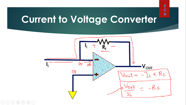
Opamp Current to Voltage Converter In this blog, I will explain Opamp Current to Voltage Converter, Why do we need current to voltage converter and application of Current to Voltage Converter. The complete explanation can be watched in video link given below. Understanding Transimpedance Amplifier : - Since no current enters the inverting input terminal and all of the current flows through the feedback resistance Rf on its way to output node. - The noninverting input terminal is connected to ground and we can assume inverting input is connected to ground due to virtual ground. -Since one side of feedback resistance Rf is connected to ground and other side is connected at Vout. So by ohms law the magnitude of output voltage is equal to the input current times feedback resistance. -The input to output relationship of transimpedance amplifier is given by: Vout = -Ii X Rf Vout/Ii = -Rf  where Vout/Ii equal to transimpedance  Transimpedance Amplifier vs Resistor : Why do we need Transimpeda

Opamp Constant Current Source Design

Image
Opamp Constant Current Source Design In This blog I will explain constant current source design using operational Amplifier. The explanation is also available in Video link given below in the blog. Above is the basic circuit diagram of constant current using opamp. Due to virtual ground concept voltage at inverting terminal is zero. Current flowing through inverting terminal is zero because input terminal of opamp is very high. Assume : Ii = Current flowing the resistance R1 = Input current IL= Current flowing through Variable resistance R3 = Load Current Since No current will flow through opamp inverting terminal and hence Ii = IL Ii = Vin/R1 and hence IL = Vin/R1 So if Vin and R1 is fixed Ii remained constant even if load R3 changes. In spite of changing the load R3 the Ii remained constant.  Application : Opamp constant current source is used in LED droving as per below circuit. The complete explanation can be seen in below video: Thanks !!!

LT Spice - Opamp Shunt Voltage Regulator Simulation

Image
              LT Spice - Opamp Shunt Voltage Regulator Simulation In This blog, 12V Power Supply Designed using LT Spice Simulation. For Complete explanation please watch the video. Please leave your comments for any queries. Thanks !!!

Op-Amp Shunt Voltage Regulator Design

Image
Op-Amp Shunt Voltage Regulator Design Fig.1 In this blog i will be explaining about the design of a Opamp shunt voltage regulator. Pros and Cons of the shunt voltage regulator will be discussed. The complete explanation can be watched in video below. Working :  Due to variation in input voltage Vin or load current IL there is a change in output voltage of shunt regulator. Terminology Used : Vin = Input Voltage Vo =Output Voltage Vz = Fixed Reference Voltage R1 & R2 = Sample or Voltage monitoring Circuit Opamp- Error Amplifier Rs = Input Current Limiting resistor Vs = Voltage across Rs Transistor = It is used to regulator the output voltage RL = Load Resistance IL = Load current Is = Source Current Ic = Transistor collector current V+ = Voltage at Non Inverting Terminal V- = Voltage at Inverting Terminal Case 1: If the output voltage increases due to sudden change in input voltage or load current. Since sample circuit monitor the output voltage using voltage divider R1 and R2. The V

Comparators - Opamp Technology Trending News

Image
Comparators -Opamp Technology Trending News Comparators : -High Speed Comparator -High Voltage Comparator -Small Size Applications : -Ideal for voltage monitoring • Over voltage protection • Battery under-voltage  detection -Current Measurement -Temperature Sensing -ZCD (Zero Cross Detection) for event monitoring  e.g. LM339, LM2901, TLV6703 LM339 -  Quad General Purpose Low-Voltage Comparators LTLV6703 -  Comparator With Integrated Reference